
T-Scann 8 - project page
Super 8 / Regular 8 film scanner
Instructions on mounting parts.
Capstan‐wheels
FilmGate
Phototrans‐upper
Phototrans‐lower
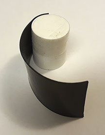
First apply double-sided adhesive tape, then tape such as those used on the Tennis and badminton racket to get a firm grip with your hand.
Such tape has high friction and it is important on the capstan wheel. If you need to change the tape, it will be easy as it is adhesive tape.
Try with a film strip that the film runs easily and smoothly, if not file the lower part do not file too much so it is loose in height. Also try with the white starting strip at the beginning of the film may be slightly thicker. When you are happy, take a coarse sandpaper and polish on the film web so it becomes a little smoother.
Normally, such parts are made of metal, but we solve this with thin aluminum foil as used in the kitchen. Apply some glue and then glue on the aluminum foil, cut off excess foil with a sharp knife. The plastic layer on the film will run over the aluminum foil, the emulsion on the film then ends up closest to the camera.
Traction‐stop

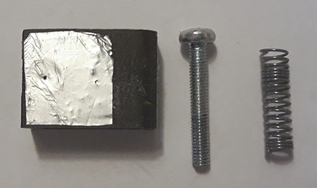
The arrow shows a small sheet metal screw, M3.5 x 5 mm, glue on a small piece of aluminum foil that is folded over the edge. The aluminum foil on the arm and the screw in the box, form a switch. Other screws M3 x 20mm + nut.
The cover for the arm and spring fastened with double-sided adhesive tape. The spring is from a larger ballpoint pen is adjusted so it does not become too heavy.
The wheel on the left "Traction-stop-E" attached to an M3 x 30mm screw with nut on the arm
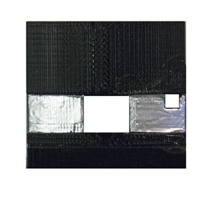
Here we use the same aluminum foil, to cover the phototransistor. Make a small hole with a sewing needle or something so that there is a hole about 0.3 mm. Now the phototransistor registers only a small part of the film perforation.
Screw M3 x 19mm and spring from a ballpoint pen, used for height adjustment, plug in screw from top then wood on screw below.
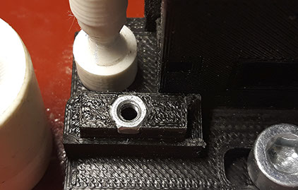
This is the lower bracket, for the part that holds the phototransistors. It is an M3 nut that is glued with Super epoxy or similar 2 component glue and then pressed
Phototrans‐protection
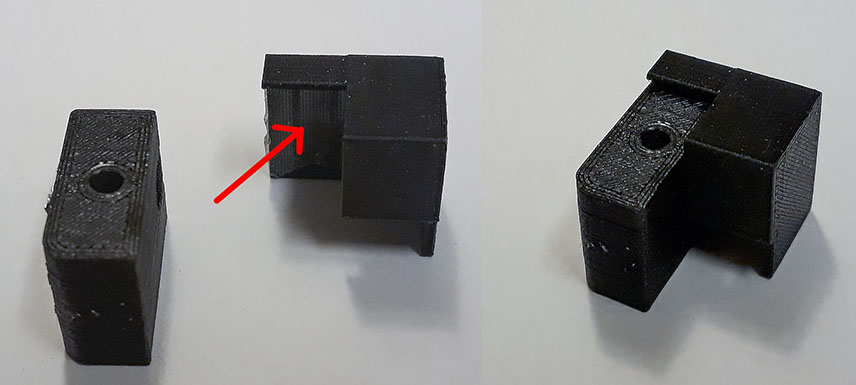
The center of the image shows the light protection for phototransistors. Apply a small piece of double-sided adhesive tape to attach it to the Phototrans ‐ upper (back)
Screw-protection-nut
Attach‐lens.stl / lens adjustment.stl / Attach‐lens‐bracket.stl

This M3 X 40mm screw replaces the short M3 screw that holds the stepper motor
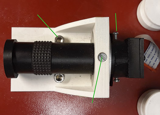
M6 X 20mm 2 pieces
M4 X 6mm
3 pieces hold the lens
metal screw, M3 x 4 mm
2 pieces
lens adjustment.stl on the left side of the lens, this height adjustment is needed when switching between super8 and Regular8. It is only a 1-2 mm adjustment so this simple construction works. You may need to apply a few thick pieces of tape to the back of the Attach lens
Camera‐mount.stl
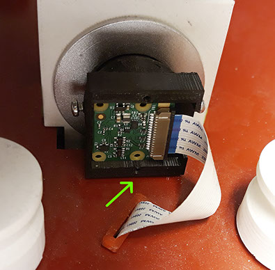
Camera ‐ mount.stl where the Rapberry PI camera V2 will be located. If necessary, file the edges so that the camera fits in easily and smoothly.
The arrow shows holes for screws cover 2 pieces of sheet metal screw M2.6 X 5.5mm. The flat cable goes down in the Flat ‐ cable ‐ bushing.stl More about the camera mounting on the side Chassis structure.
Filmgate is glued together
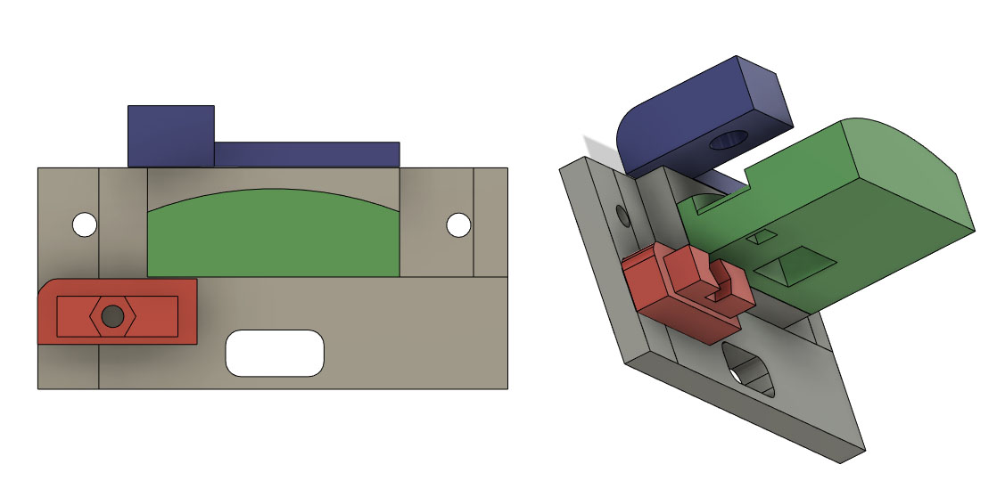
The parts FilmGate, Ground ‐ gate, Phototrans‐lower and White ‐ Led ‐ attachment are glued together with Super epoxy or similar, glue part by part and let dry
An Insex screw M6 X 15mm is inserted in the elongated hole. This goes through the plate to the "Filmgate ‐ bolt ‐ bracket" and an M6 nut.